 share on Buffer
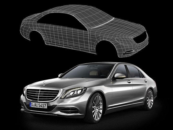
Differently from most 3D modeling tutorials available, Ali Ismail‘s guide – republished here courtesy of its author – gives detailed information specific for achieving high-quality surfaces and reflections, suitable for automotive and product design visualization.
It also makes an interesting comparison, including technical remarks, between NURBS and polygonal/subdivided geometry, which is crucial to fully understand the potentials and the limits of each technique.
This is much more than a quick time-lapse video nor a step-by-step guide – it’s an in-depth lecture targeted to intermediate and advanced modelers.
We suggest you to bookmark the page, study it and refer back to it when needed.
Thanks again to Ali Ismail for sharing his knowledge and for letting us republish his article here.
Sections
Introduction
This tutorial examines the creation of polygonal meshes with high quality curvature to produce better reflections.
Artists who have experience in modeling complex polygon hard surfaces such as cars but are looking to have a better grasp on the subject will benefit more of this tutorial. Hopefully it will also give you an understanding of the challenges involved in creating a car model and why many prefer to use NURBS to accomplish this task. By using the example of a car body, you can apply the same principles to any reflective object whether it is a boat, a futuristic concept train or a sophisticated water faucet.
While this is a car modeling tutorial, it will not go into any details of the basic process of creating the mesh, specific tools or matching the reference proportions which I feel are better suited for a general modeling or hard surface modeling tutorial, you should note that the level of quality this tutorial deals with relates to rendering an object with continuous reflection streaks across it. If all what you are after is an object reflecting an HDR sky environment and you don’t mind some reflection distortions, that the untrained eye won’t catch, then this is not for you.
One reason for creating this tutorial was another tutorial that I have created many years ago when I was starting out my way in 3D graphics (Making of Mercedes S600 (PDF 7.0MB)). I felt that a follow up is necessary to go into the depths of understanding the intricacies of automotive modeling and laying out the basic principles which distinguishes it from any other type of 3D modeling.
Class A Surfacing
Perhaps, the biggest defining characteristic of a car body is the fact that it is reflective! Highly reflective surfaces clearly expose your model curvature unlike matte objects. Imagine a dent or bump on a mirror versus on a dusty wooden cabinet.
Note: for all intents and purposes of this tutorial you could define a class A surface as a surface which reflects really nicely.
if you go into car or industrial modeling for actual manufacturing, where you will be using a NURBS modeling software similar to Autodesk Alias or Rhinoceros 3D, you are bound to run into terms like tolerance and continuity. All the industrial technical details put aside what we are interested in for creating a car for rendering, is continuity, that refers to how continuous a reflection is across a surface.
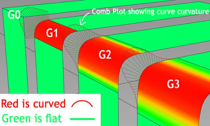
- Position continuity (G0): the surfaces are aligned and have no gaps in-between.
- Tangential continuity (G1): There are no sharp edges in-between the surfaces.
- Curvature continuity (G2): the surfaces are blended together with the highlights appearing as if its on a single surface.
- Rate of curvature change (G3): its even more blended but the difference is very small and hardly noticeable.
To learn more about NURBS, I have a basic introduction into NURBS article which you can check or you can start exploring on your own using the term “class A surfacing” in any search engine. Below are few more links you can go through.
Back to Polygons
Taking the surfaces back into any polygon modeling software, we can attempt to replicate the same curvature using very simple geometry and applying a typical Catmull-Clark subdivision and get somewhat close to the original.
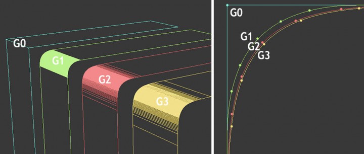
Download the scene here 3ds Max 2010 | OBJ (right click and save target as)
Now, just because we can get an approximation with polygons does not mean that we are creating an accurate reflection continuity.
If you try it yourself or open the scene above you would see how difficult it is to match a NURBS surface with a Catmull-Clark subdivided mesh because the two are using very different algorithms. Please note that we didn’t test a complicated surface. We can conclude from all the above-mentioned information that reflections are important and moving a vertex or a loop even in small amounts could affect the result in great proportions.
The Horror!
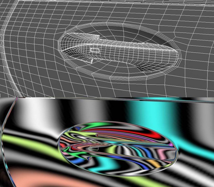
Below are close-ups of a car render, anyone who had experience in rendering cars modeled in polygons will be familiar with this.
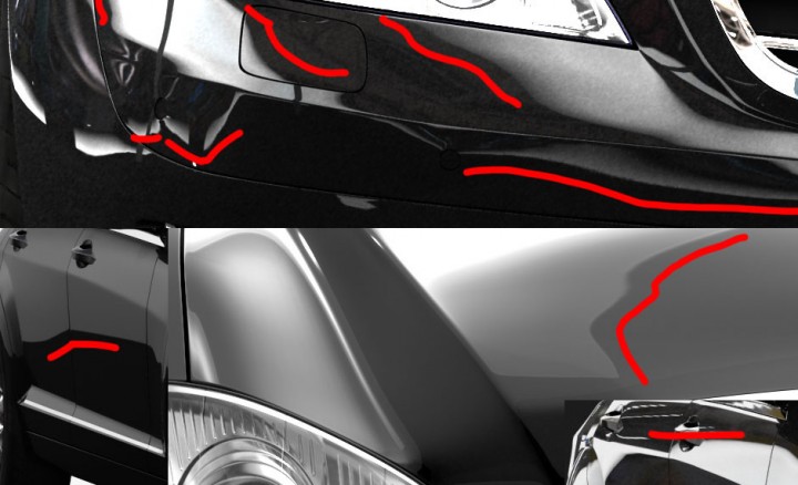
So, you have a nice mesh with good looking edge loops and you wanted to make a high resolution render in an indoor environment. To your dismay, you are faced with a dilemma of wavy and jagged reflections.
You could try to decrease its effect by moving the reflection boxes closer to the mesh making it almost a diffuse texture, but then if you are doing an animation where you wanted the highlights to sweep across the car body.
There is no getting around it, unless you do very time consuming rotos in composite [rotoscoping, i.e. removing/masking out imperfections during post production] and basically painting the reflections for an animation length. All this can be avoided if you had a good model to start with.
Some of the artifacts above might be due to slightly misplaced vertices but for the most part the cause is much more subtle. Please Observe this effect:
So as you can see a pole, a simple cut or even an edge loop could cause considerable artifacts in reflections.
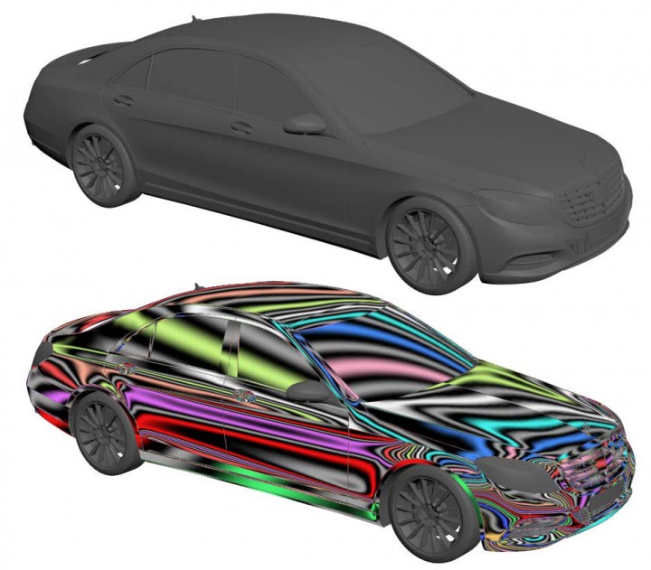
Below are some examples of car bodies which have “clean” topology and yet show similar waviness or jaggedness in the reflections.
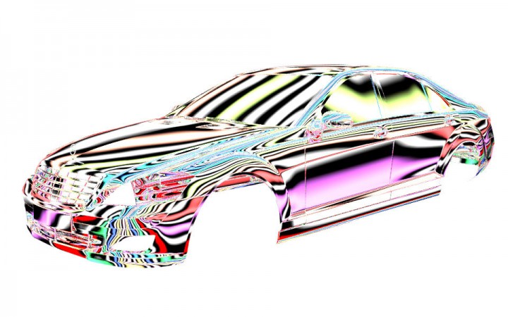
Note: Download the HDRI or cubemap used in this tutorial FlowCheck.HDR 4.92 MB | FlowCheck.DDS 192 KB (right click and save target as).
You can easily create a similar one using HDR Light Studio and if you are interested in real-time engines or cubemaps you can check any of those two tutorials to know how to convert an HDRI to a cubemap: CGTextures tutorial | Xoliul tutorial.
Tool tip:
3ds Max: To view reflection maps interactively in the viewport, In Views menu under Show Materials in Viewport As select Realistic Materials with Maps. If you want to explore with further real-time capabilities in 3ds Max you can check Xoliul Shader by Laurens Corijn and Robbert-Jan Brems.
Root Cause
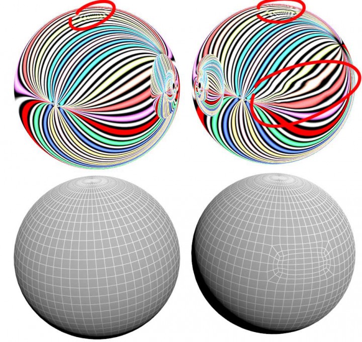
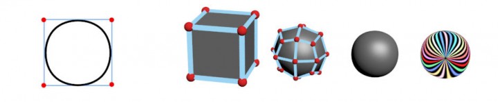
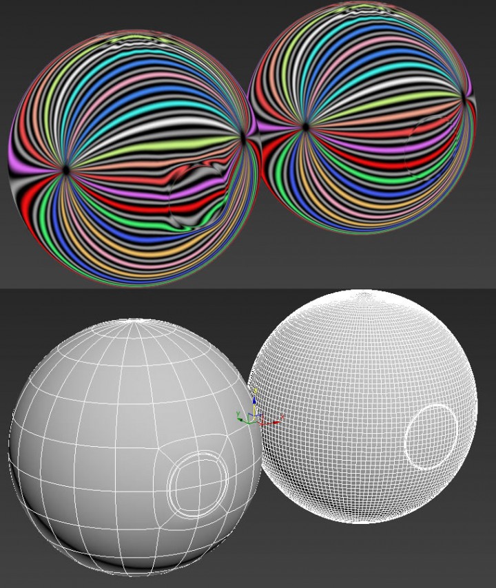
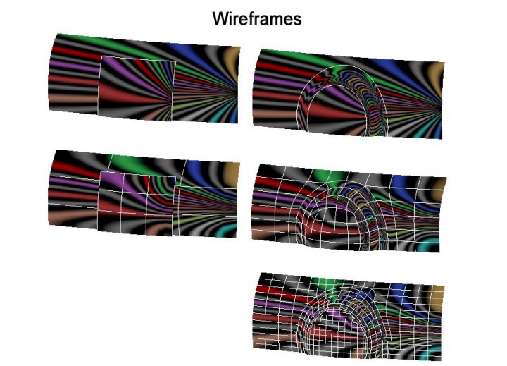
If you take a cube, subdivide it enough, and you will get something close to a sphere. (Catmull-Clark subdivision)
Below you can see an example of how curvature changes when you create a cut in a mesh (or a vertex into an edge) and subdivide it.
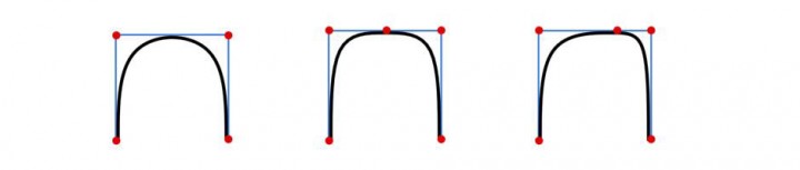
It’s quite natural for it to behave in this fashion. But this of course, explains why creating an extra loop or cut can change curvature or distort it and why it can be very difficult to model a polygon mesh with good reflections.
This is what happens when we start hitting polygon modeling limitations, the effect cannot be avoided completely using polygons, but it can be mitigated to some extent.
Models designed in NURBS with class A surfacing techniques show perfect reflections, and the machines creating the molds for the car body panels can trace the surface as good as it’s physically possible, thus producing a flawless mold that metal sheets can be pressed onto resulting in a surface that is accurate enough to give continuous reflections. CAD data also have exact tolerances for all the screws and tight fitting mechanical hardware.
Let’s hope that later on, it would become common to see integration of a new type of subdiv surfaces, which can be used for manufacturing, with proper modeling tools for measurement, blends and fillets combined with some smart tricks that can solve these issues.
Solutions
How far you will go to reduce this effect is up to you, it’s important to keep your final goal in mind. You will decide whether you want a reflection as good as possible or if you want to have a cleaner mesh. Are you creating this for a still image? how many images? can you fix reflection flaws in Photoshop or are you doing an animation? or do you just enjoy modeling cars and have an obsessive drive to make the perfect car and insist on using polygons!
As you will find out by the end of this tutorial, if what you are after is a true class A surface car body, then you better stick with a high-end NURBS modeling tool.
This does not mean that with little practice you couldn’t create a polygon mesh that reflects nicely. That polygon mesh could come in handy, especially when what you need is modeling a car for a video game with high polygon count.
Before moving into any complicated objects like a car, its better to make sure we can create simple ones first and review some practices.
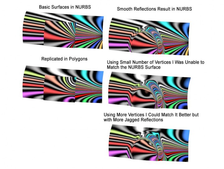
TIP #1: Use as few vertices as possible
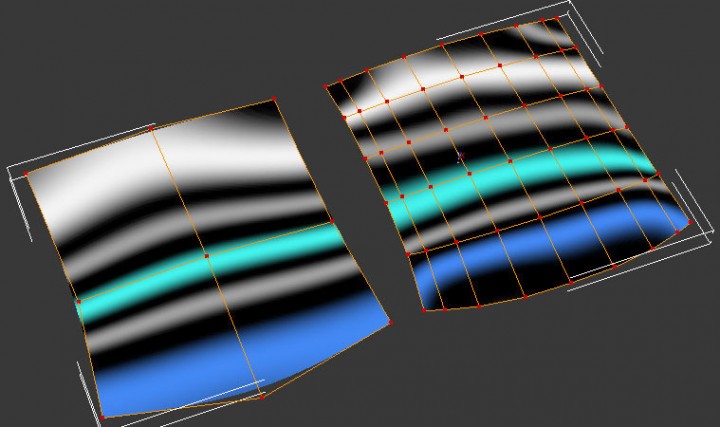
Getting by the least amount of vertices makes it possible to easily create flowing reflections and to later edit the surface.
Even though I tried to place the vertices of the surface on the right as well as I could I was unable to get the same quality of reflection as the one on the left with very few vertices.
Tip #2: Try to evenly space edge loops or to use any curve tools available for vertices or to make the change in edge loops density gradual
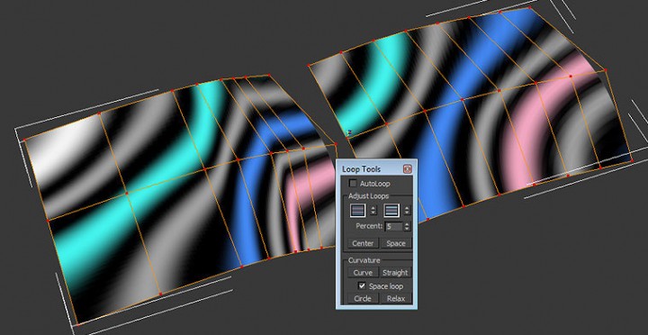
Proper edge spacing and positioning the vertices to follow a curve could greatly improve reflections. In 3ds Max you can use the loop tools to do so.
Tip #3: Make any trims or cuts across any surface only after you have finalized the surface and have sufficient subdivisions
Any trims made on the low poly surface makes drastic changes to the curvature, to minimize artifacts and as a measure of damage control, making the trims or cuts after subdivision will reduce the artifacts.
In fact, once you realize this, you are a step closer to modeling and thinking in NURBS. In NURBS, trims are an integral part of the process.
This effect, can be typically seen in the door handle area of a car, where polygon cuts and all fine detailing have been made on the low poly mesh. I have seen many artists, who subdivide the car doors one or two levels higher than the rest of the mesh then create the trims, just to make sure they have important reflections on the side of the car running smoothly.
No Support Loops
 For the final mesh I am going to use as an example at the end of this tutorial, I did add support loops, but only at the very end. The workflow am suggesting here is a method to add to your toolkit and not the be-all and end-all of hard surface modeling.
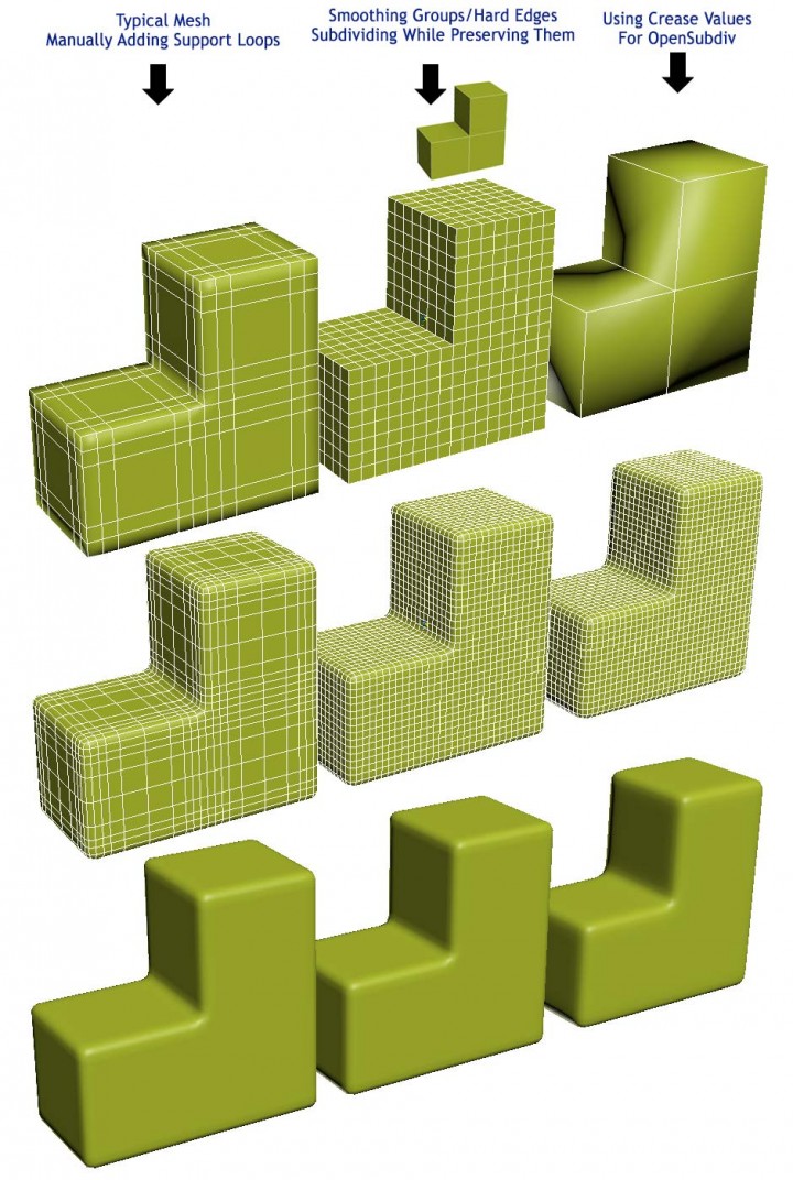
A general method to speed up the modeling process, that I use not only for cars or hard-surfaces, but also for modeling anything really, is to to use fewer edge loops as possible in the start and try to get the support loops for free by using hard edges.
Not only is it time consuming to add support edge loops manually but it would be much harder to modify the base mesh and focus on the curvature of the surface.
OpenSubdiv makes it easy to control our creases but even without it we can still preserve our hard edges using hard edge/crease/smoothing groups and preserving the hard edges when doing a standard Catmull-Clark subdivision. This enables us to shape the basic forms with minimum effort.
Note: Long before Autodesk OpenSubdiv hype we had a plug-in by Marius Silaghi called TurboSmooth Pro which did basically the same thing. Please view his website to check this plug-in and other interesting and useful plug-ins.
Tool tip:
3ds Max: Set smoothing groups to define your surface then add a MeshSmooth/TurboSmooth with Smoothing Groups ticked Or if using OpenSubdivadjust the edges Crease values manually in the Editable Poly Edit Edges Tab. I have noticed some bugs in 3ds Max where sometimes you see a strange subdivision artifact if using smoothing groups, always double check your mesh and look at the resulting wire-frame and if you notice anything wrong you can fix by deleting the surface and rebuilding the polygons again or as a safe measure by exporting into OBJ and importing again.
Maya: Either use the Crease tool from the Mesh Tools menu and apply OpenSubdiv Subdivision type or select your edges and from the Normals menuselect Harden Edge then Select Smooth Options and use Maya Catmull-Clark as Subdivision type and make sure the Hard edges check box is ticked under preserve tab.
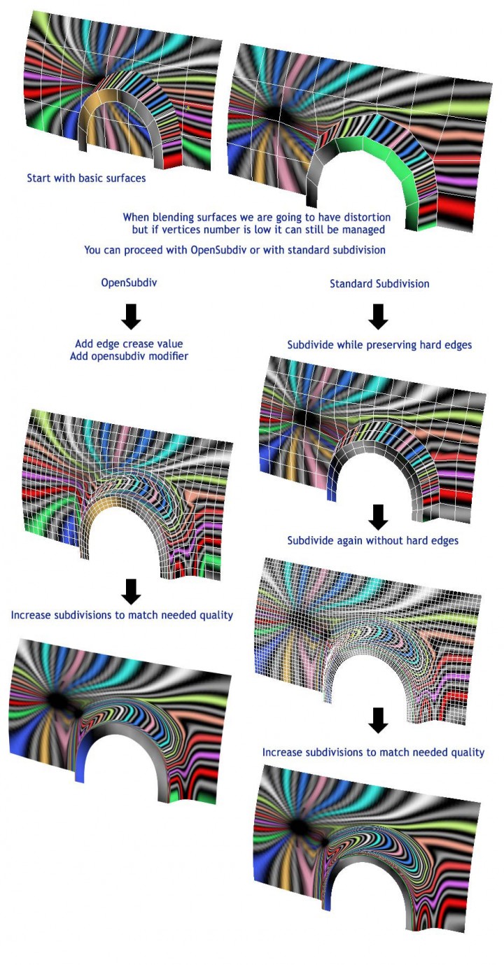
Blending Surfaces
It all looks good in theory: use few vertices, good spacing and trim after finishing the mesh, but when you start modeling a car you will find it’s not as easy to apply.
Cars have complex surfaces, where curvature is done with great care, surfaces are trimmed at an early stage and blended seamlessly with other surfaces.
I am not suggesting that you start creating your mesh in separate surfaces instead of aiming to the poly-mesh you see suitable, but it helps to understand while Its easy to create simple surfaces on their own that reflect properly, we are almost always forced to have complex ones that could cause distortions.
Replication Test
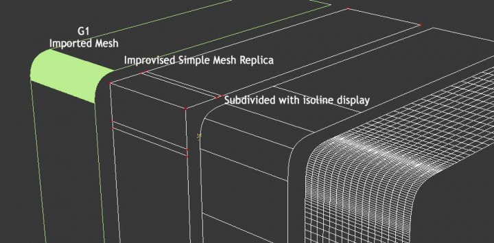
I created a simple NURBS object in Alias Automotive, which could represent a wheel arch area in a car and imported it back in max. You can see below my attempt to replicate it in polygons.
In answer to Craig Kitzmann, who wondered if it would help to create a surface in NURBS then retopologize it in polygons.
The response seems to be in the negative. If you do create it in NURBS, you would really have to justify any retopolgy process, you can simply import the wire file, or convert it to any format into your prefered 3D tool and render it from there directly.
And If you need a simple mesh for real-time use; then the NURBS one wouldn’t help either and you better save your effort and do it all inside a polygon modeling software.
These polygon methods can still be very helpful in creating concepts and design ideas, if you are experienced in handling polygons, you can create basic shapes quickly and test them out.
Process
The simple wish to improve polygon meshes curvature, to produce better reflections have led us through the rabbit hole of learning about NURBS and different subdivision methods.
A car/boat/airplane body is very complex with many surfaces intersecting and blending. Please note, even if you use a NURBS tool to create your model, its not going to be always straight forward to create continuous reflections, especially if you are aiming at a class A surface quality, for cars; certain areas like wheel arches and pillars require some practice. Sometimes achieving a G2 continuity with a tight tolerance could feel like winning a lottery!
In no shape or form am I pretending that we could create G2 or G3 continuities in polygons, but what I am attempting is to create a representable reflective surface, mainly in the bigger parts such as car side panels, roof and bonnet and avoid distortions which are easy to fix.
The model I am presenting here could have been better created. Maybe without few edge loops here or there, and there are few areas which I could have made a better topology at or perhaps made some trims at a higher subdivision to avoid reflection artifacts. That said, all in all I am very happy with the improvements I made over my previous car models.
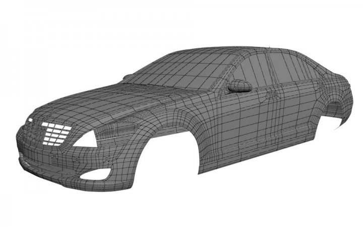
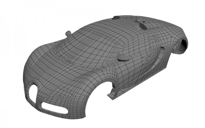
Step 1 – Create a Base Mesh
This is by far the most important step, It’s where you make it or break it. the topology looks simple but its well thought out.
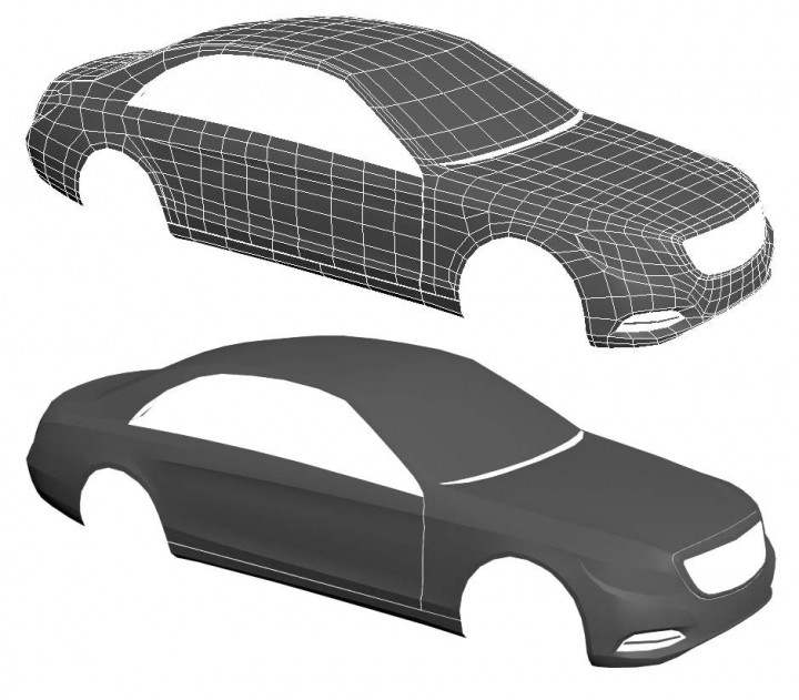
The mesh created at this stage would look very similar to what you see used in games with a low poly count. If I added few more loops I could even get away with a high quality model without using any subdivisions, only carefully using smoothing groups/hard edges.
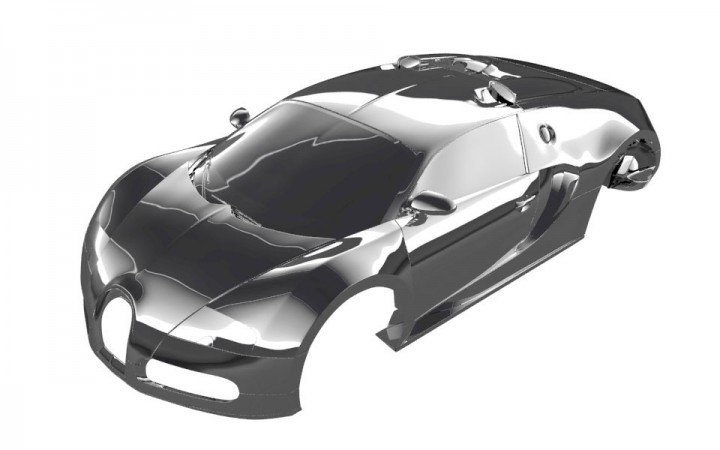
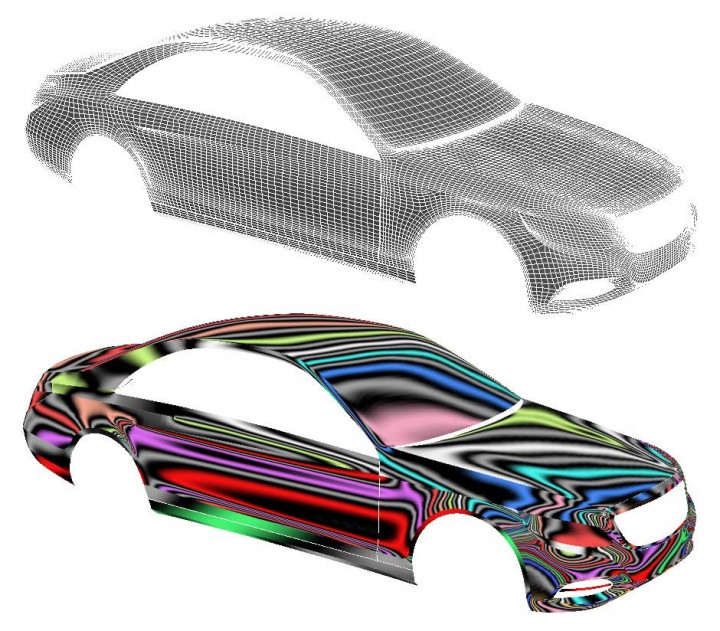
Step 2 – Subdivide and Do a Flow Check
Add your subdivisions while preserving hard edges, or experiment with crease values for OpenSubdiv, doing reflection tests and continually going back to the base mesh until you are absolutely certain that the mesh quality is at the level you are looking for.
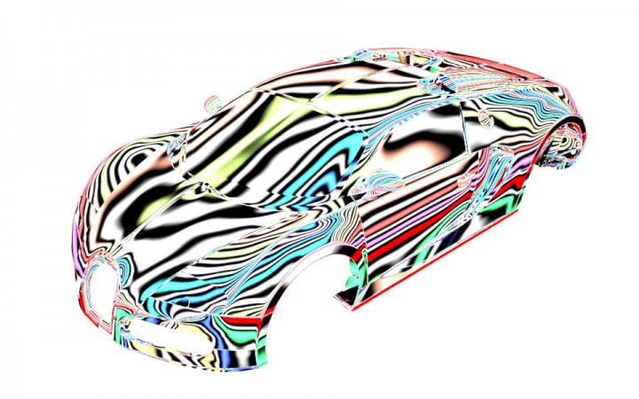
Step 3 – Finalize
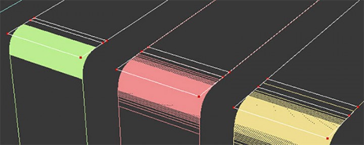
Choose the subdivision level you feel the trims won’t cause a considerable distortion at (below you can see the wire-frames of the one I chose), and start adding trims, details and support loops.
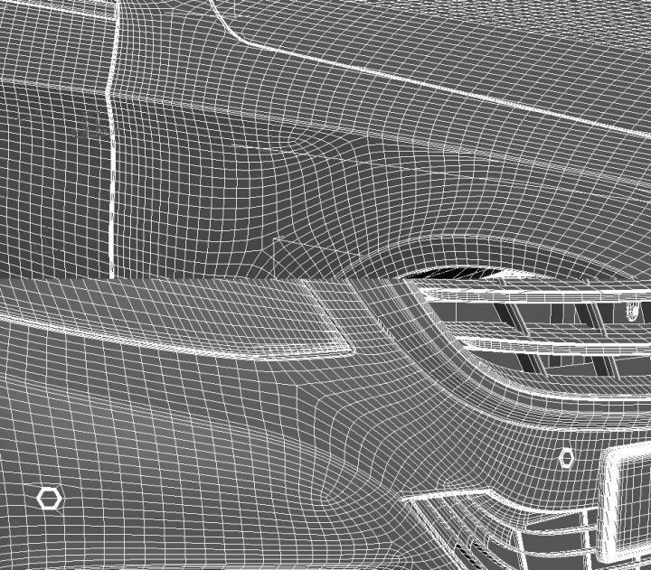
Please be aware that once you stat adding trims there is no going back to the original base and you can’t modify or change anything.
Achilles’ Heel
Just to point out the few “problem” areas I have in this mesh that you could detect directly from the flow check reflection map.

These might seem trivial and unimportant, but as you will observe in the final image they could have a considerable effect. Of course it depends on the reflection/light box placement and camera angle but if you happen to have a reflection stripe going through an artifact area its going to show.
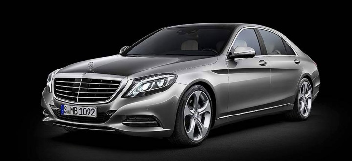
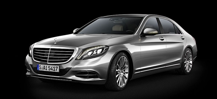
Reference
This is the reference image I used for rendering this car. Almost all indoor studio car photos are heavily manipulated nowadays so you can’t be completely sure of the reflections you see on the car. Yet they can serve as a good guideline.
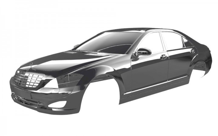
Render
You see here that in my final render around the wheel arch where you previously saw a tiny artifact the effect is noticeable and I had to Photoshop it out, For an animation I would either have to fix it in comp or redo that panel mesh at the base level.
Final render after post-precess in Photoshop. To view the high resolution render click here
References
Other than 3DTotal and CGFeedback forums which are great for checking finished works and in progress ones you can search for web forums specialized in car modeling.
Two websites which I highly recommend would be SMCars.net especially the advanced WIP section which has some threads that are a treasure trove for 3D car modelers, and the 3D tutorials section at CarBodyDesign.com.
Thank you for reading this tutorial and I hope part of the information here was of any help. if you find anything that can be improved upon please do drop me an E-mail.
Note: the article was published originally at aliismail.com and is republished here on Car Body Design courtesy of the author.
About the Author
Ali Ismail is a freelance CG artist dedicated to the improvement of his skills. He had experience working with ILM, LucasArts and Pixomondo.
Contacts
- website: aliismail.com
(Images and text courtesy of Ali Ismail)


From the Author,
Thank you for reading. For the latest version of this tutorial which I continually update please visit:
https://www.ebalstudios.com/blog/modeling-cars-polygons
Nice tutorial. I really like the graphics.
Thanks for the feedback, yes, it’s a great tutorial. You can also check his other tutorials at https://www.ebalstudios.com/tutorials/
Thanks. Could you also post some of them on hackr. It would be easy for us new designers to find.
https://hackr.io/tutorials/learn-autodesk-3ds-max